今天我们来配置基于 BGP-EVPN 控制的 VXLAN 网络。
拓扑整图如下:
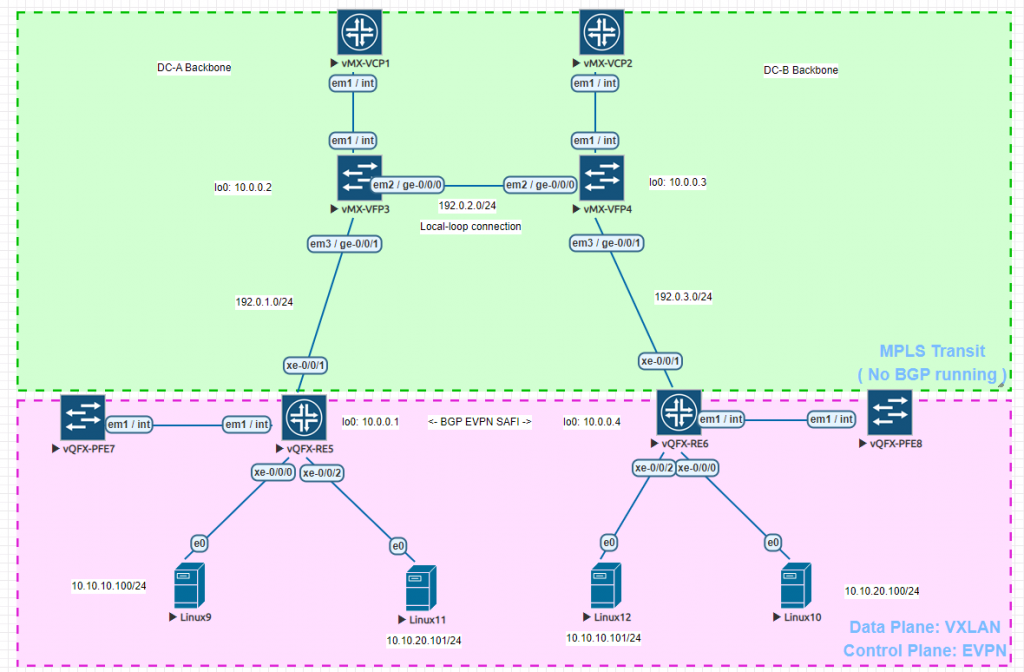
数据中心需求:
- DC-A 需要和 DC-B 通过 Localloop 进行互联成一张大内网
- 交换机下二层域需要合并为逻辑上的一张整二层域(两地交换机需要合并成一个二层域)
一般来说,将二层域互联,有以下几个技术:
- VPLS
- MPLS L2 Circuit
- VXLAN
首先来说 VPLS,VPLS这技术的确不错,但是用法比较局限,受拓扑影响比较大,且并不是每个三层交换机都支持。L2 circuit 不太适合这样的场景,我更觉得它比较适合用于点对点的传输情形下的使用,而 VXLAN 因为能像传统 VLAN 一样进行流量的隔离,就比较适合于数据中心互联的场景,且现代的交换机基本都会支持该功能。
话不多说,我们来进行配置。
首先配置 Underlay 网络,由于是数据中心互联,所以我们 Underlay 直接使用 OSPF 作为 Basic protocol,MPLS 作为 L2.5 封装,确保 Underlay 网络能传输 EVPN 数据。
请注意:本实验拓扑实际上不会用到 MPLS 作为传输,纯 IGP 路由传输即可完成需求。但是为了之后的实验 ( MPLS L2 Circuit ) ,请按照教程开启 MPLS address-family 以及 LDP 信令协议。
请在配置 Underlay 网络前将接口 MTU 设置为 9000 ( 若不支持设置为 9000,则需要设置一个大于 1550 的值 )。
DC-A vMX:
root> show system rollback compare 4 0
[edit]
+  interfaces {
+      ge-0/0/0 {
+          unit 0 {
+              family inet {
+                  address 192.0.2.1/24;
+              }
+              family mpls;
+          }
+      }
+      ge-0/0/1 {
+          unit 0 {
+              family inet {
+                  address 192.0.1.2/24;
+              }
+              family mpls;
+          }
+      }
+      lo0 {
+          unit 0 {
+              family inet {
+                  address 10.0.0.2/32;
+              }
+          }
+      }
+  }
+  protocols {
+      mpls {
+          interface ge-0/0/0.0;
+          interface ge-0/0/1.0;
+      }
+      ospf {
+          area 0.0.0.0 {
+              interface ge-0/0/0.0;
+              interface ge-0/0/1.0;
+              interface lo0.0;
+          }
+      }
+      ldp {
+          transport-address 10.0.0.2;
+          interface ge-0/0/0.0;
+          interface ge-0/0/1.0;
+      }
+  }
DC-B vMX:
root> show system rollback compare 3 0
[edit]
+  interfaces {
+      ge-0/0/0 {
+          unit 0 {
+              family inet {
+                  address 192.0.2.2/24;
+              }
+              family mpls;
+          }
+      }
+      ge-0/0/1 {
+          unit 0 {
+              family inet {
+                  address 192.0.3.1/24;
+              }
+              family mpls;
+          }
+      }
+      lo0 {
+          unit 0 {
+              family inet {
+                  address 10.0.0.3/32;
+              }
+          }
+      }
+  }
+  protocols {
+      mpls {
+          interface ge-0/0/0.0;
+          interface ge-0/0/1.0;
+      }
+      ospf {
+          area 0.0.0.0 {
+              interface lo0.0;
+              interface ge-0/0/0.0;
+              interface ge-0/0/1.0;
+          }
+      }
+      ldp {
+          transport-address 10.0.0.3;
+          interface ge-0/0/0.0;
+          interface ge-0/0/1.0;
+      }
+  }
DC-A QFX:
root@vqfx-re> show configuration interfaces xe-0/0/0
unit 0 {
    family ethernet-switching {
        interface-mode access;
        vlan {
            members cust;
        }
    }
}

{master:0}
root@vqfx-re> show configuration interfaces xe-0/0/2
unit 0 {
    family ethernet-switching {
        interface-mode access;
        vlan {
            members cust2;
        }
    }
}

{master:0}
root@vqfx-re> show configuration interfaces lo0
unit 0 {
    family inet {
        address 10.0.0.1/32;
    }
}

{master:0}
root@vqfx-re> show configuration interfaces irb
unit 100 {
    family inet {
        address 10.10.10.253/24 {
            virtual-gateway-address 10.10.10.1;
        }
    }
}
unit 200 {
    family inet {
        address 10.10.20.253/24 {
            virtual-gateway-address 10.10.20.1;
        }
    }
}

{master:0}
root@vqfx-re> show configuration vlans
cust {
    vlan-id 100;
    l3-interface irb.100;
}
cust2 {
    vlan-id 200;
    l3-interface irb.200;
}

{master:0}
root@vqfx-re> show configuration protocols ospf
area 0.0.0.0 {
    interface xe-0/0/1.0;
    interface lo0.0;
}

{master:0}
root@vqfx-re> show configuration protocols ldp
transport-address 10.0.0.1;
interface xe-0/0/1.0;

{master:0}
root@vqfx-re> show configuration protocols mpls
interface xe-0/0/1.0;
DC-B QFX:
root@vqfx-re> show configuration interfaces xe-0/0/0
unit 0 {
    family ethernet-switching {
        interface-mode access;
        vlan {
            members cust2;
        }
    }
}

{master:0}
root@vqfx-re> show configuration interfaces xe-0/0/2
unit 0 {
    family ethernet-switching {
        interface-mode access;
        vlan {
            members cust;
        }
    }
}

{master:0}
root@vqfx-re> show configuration interfaces irb
unit 100 {
    family inet {
        address 10.10.10.254/24 {
            virtual-gateway-address 10.10.10.1;
        }
    }
}
unit 200 {
    family inet {
        address 10.10.20.254/24 {
            virtual-gateway-address 10.10.20.1;
        }
    }
}

{master:0}
root@vqfx-re> show configuration interfaces lo0
unit 0 {
    family inet {
        address 10.0.0.4/32;
    }
}

{master:0}
root@vqfx-re> show configuration vlans
cust {
    vlan-id 100;
    l3-interface irb.100;
    vxlan {
        vni 100;
        ingress-node-replication;
    }
}
cust2 {
    vlan-id 200;
    l3-interface irb.200;
    vxlan {
        vni 200;
        ingress-node-replication;
    }
}

{master:0}
root@vqfx-re> show configuration protocols ospf
area 0.0.0.0 {
    interface lo0.0;
    interface xe-0/0/1.0;
}

{master:0}
root@vqfx-re> show configuration protocols ldp
transport-address 10.0.0.4;
interface xe-0/0/1.0;

{master:0}
root@vqfx-re> show configuration protocols mpls
interface xe-0/0/1.0;

{master:0}
配置完成,我们来检查下 Underlay 网络:
DC-A vMX:
root> show ldp neighbor
Address                             Interface       Label space ID     Hold time
192.0.2.2                           ge-0/0/0.0      10.0.0.3:0           10
192.0.1.1                           ge-0/0/1.0      10.0.0.1:0           14
DC-B vMX:
root> show ldp neighbor
Address                             Interface       Label space ID     Hold time
192.0.2.1                           ge-0/0/0.0      10.0.0.2:0           11
192.0.3.2                           ge-0/0/1.0      10.0.0.4:0           13
DC-A QFX:
root@vqfx-re> ping 10.0.0.4 source 10.0.0.1
PING 10.0.0.4 (10.0.0.4): 56 data bytes
64 bytes from 10.0.0.4: icmp_seq=0 ttl=62 time=133.250 ms
64 bytes from 10.0.0.4: icmp_seq=1 ttl=62 time=147.078 ms
64 bytes from 10.0.0.4: icmp_seq=2 ttl=62 time=100.059 ms
^C
--- 10.0.0.4 ping statistics ---
3 packets transmitted, 3 packets received, 0% packet loss
round-trip min/avg/max/stddev = 100.059/126.796/147.078/19.731 ms
既然 LDP neighbor 已经 UP 了,且互相 Ping 已经通了,说明 Underlay 网络已经配置成功。现在让我们来配置 Overlay 网络。
DC-A QFX:
root@vqfx-re> show system rollback compare 2 0
[edit]
+  routing-options {
+      router-id 10.0.0.1;
+      autonomous-system 65000;
+  } // 预配置 BGP Router-id 与 本地 ASN
[edit protocols]
+   bgp {
+       group evpn {
+           type internal;
+           local-address 10.0.0.1;
+           family evpn {
+               signaling;
+           }
+           neighbor 10.0.0.4;
+       }
+   } // 激活 EVPN Signaling,使其能够与邻居交换 MAC/IP 数据并建立 VTEP 之间的连接
+   evpn {
+       encapsulation vxlan; // 配置 EVPN 协议封装模式为 VXLAN
+       extended-vni-list all; // 发送所有 VNI 信息,可以设置为只发送特定 VNI info
+       multicast-mode ingress-replication;
+       vni-options {
+           vni 100 {
+               vrf-target export target:65000:100; // 发送该 VNI 时候携带 target:65000:100 这个 extend community
+           }
+           vni 200 {
+               vrf-target export target:65000:200; // 同上
+           }
+       }
+   }
[edit]
+  policy-options {
+      policy-statement evpn-import {
+          term 100 {
+              from community v100;
+              then accept;
+          } // 接收 VNI 100 的信息
+          term 200 {
+              from community v200;
+              then accept;
+          } // 接收 VNI 200 的信息
+          term 999 {
+              then reject;
+          }
+      }
+      community v100 members target:65000:100;
+      community v200 members target:65000:200;
+  } // 定义 VXLAN Target community,下面会用到
+  switch-options {
+      service-id 1;
+      vtep-source-interface lo0.0; // 定义 VXLAN VTEP source 使用 loopback
 接口建立连接
+      route-distinguisher 10.0.0.1:1;
+      vrf-import evpn-import; // 根据上面定义的 VXLAN Target community policy 来导入 EVPN-VXLAN 信息
+      vrf-target {
+          target:65000:1;
+          auto;
+      }
+  }
[edit vlans cust]
+    vxlan {
+        vni 100;
+        ingress-node-replication;
+    } // 在 VLAN 上激活 VXLAN VNI
[edit vlans cust2]
+    vxlan {
+        vni 200;
+        ingress-node-replication;
+    }
DC-B QFX:
root@vqfx-re> show system rollback compare 2 0
[edit]
+  routing-options {
+      router-id 10.0.0.4;
+      autonomous-system 65000;
+  }
[edit protocols]
+   bgp {
+       group evpn {
+           type internal;
+           local-address 10.0.0.4;
+           family evpn {
+               signaling;
+           }
+           neighbor 10.0.0.1;
+       }
+   }
+   evpn {
+       encapsulation vxlan;
+       extended-vni-list all;
+       multicast-mode ingress-replication;
+       vni-options {
+           vni 100 {
+               vrf-target export target:65000:100;
+           }
+           vni 200 {
+               vrf-target export target:65000:200;
+           }
+       }
+   }
[edit]
+  policy-options {
+      policy-statement evpn-import {
+          term 100 {
+              from community v100;
+              then accept;
+          }
+          term 200 {
+              from community v200;
+              then accept;
+          }
+          term 999 {
+              then reject;
+          }
+      }
+      community v100 members target:65000:100;
+      community v200 members target:65000:200;
+  }
+  switch-options {
+      service-id 1;
+      vtep-source-interface lo0.0;
+      route-distinguisher 10.0.0.4:1;
+      vrf-import evpn-import;
+      vrf-target {
+          target:65000:1;
+          auto;
+      }
+  }
[edit vlans cust]
+    vxlan {
+        vni 100;
+        ingress-node-replication;
+    }
[edit vlans cust2]
+    vxlan {
+        vni 200;
+        ingress-node-replication;
+    }
现在 Overlay 网络已经配置好了,我们来检查一下。
检查 MAC Table:
root@vqfx-DC-A> show ethernet-switching table

MAC flags (S - static MAC, D - dynamic MAC, L - locally learned, P - Persistent static
           SE - statistics enabled, NM - non configured MAC, R - remote PE MAC, O - ovsdb MAC)


Ethernet switching table : 6 entries, 6 learned
Routing instance : default-switch
   Vlan                MAC                 MAC      Logical                Active
   name                address             flags    interface              source
   cust                00:50:00:00:09:00   D        xe-0/0/0.0
   cust                00:50:00:00:0c:00   D        vtep.32769             10.0.0.4
   cust                02:05:86:71:8b:00   D        vtep.32769             10.0.0.4
   cust2               00:50:00:00:0a:00   D        vtep.32769             10.0.0.4
   cust2               00:50:00:00:0b:00   D        xe-0/0/2.0
   cust2               02:05:86:71:8b:00   D        vtep.32769             10.0.0.4

{master:0}
root@vqfx-DC-B> show ethernet-switching table

MAC flags (S - static MAC, D - dynamic MAC, L - locally learned, P - Persistent static
           SE - statistics enabled, NM - non configured MAC, R - remote PE MAC, O - ovsdb MAC)


Ethernet switching table : 6 entries, 6 learned
Routing instance : default-switch
   Vlan                MAC                 MAC      Logical                Active
   name                address             flags    interface              source
   cust                00:50:00:00:09:00   D        vtep.32769             10.0.0.1
   cust                00:50:00:00:0c:00   D        xe-0/0/2.0
   cust                02:05:86:71:ce:00   D        vtep.32769             10.0.0.1
   cust2               00:50:00:00:0a:00   D        xe-0/0/0.0
   cust2               00:50:00:00:0b:00   D        vtep.32769             10.0.0.1
   cust2               02:05:86:71:ce:00   D        vtep.32769             10.0.0.1

{master:0}
检查可知两台交换机已通过 VXLAN 学习到了彼此对端的 MAC address.
继续检查 EVPN Entries:
root@vqfx-DC-A> show route evpn-mac-address 00:50:00:00:0a:00 table bgp.evpn.0

bgp.evpn.0: 14 destinations, 14 routes (14 active, 0 holddown, 0 hidden)
+ = Active Route, - = Last Active, * = Both

2:10.0.0.4:1::200::00:50:00:00:0a:00/304
                   *[BGP/170] 02:46:16, localpref 100, from 10.0.0.4
                      AS path: I, validation-state: unverified
                    > to 192.0.1.2 via xe-0/0/1.0, Push 299808
2:10.0.0.4:1::200::00:50:00:00:0a:00::10.10.20.100/304
                   *[BGP/170] 02:46:16, localpref 100, from 10.0.0.4
                      AS path: I, validation-state: unverified
                    > to 192.0.1.2 via xe-0/0/1.0, Push 299808
root@vqfx-DC-B> show route evpn-mac-address 00:50:00:00:09:00 table bgp.evpn.0

bgp.evpn.0: 14 destinations, 14 routes (14 active, 0 holddown, 0 hidden)
+ = Active Route, - = Last Active, * = Both

2:10.0.0.1:1::100::00:50:00:00:09:00/304
                   *[BGP/170] 02:49:18, localpref 100, from 10.0.0.1
                      AS path: I, validation-state: unverified
                    > to 192.0.3.1 via xe-0/0/1.0, Push 299808
2:10.0.0.1:1::100::00:50:00:00:09:00::10.10.10.100/304
                   *[BGP/170] 02:49:18, localpref 100, from 10.0.0.1
                      AS path: I, validation-state: unverified
                    > to 192.0.3.1 via xe-0/0/1.0, Push 299808
检查 bgp.evpn.0 表可得知,均已学习到包含 MAC 地址以及主机 IP 的 Type-2 以及 Type-5 路由。
检查 Linux server(只需要检查一台即可确认状态):
root@DC-A-Linux9:~# ip nei
10.10.10.101 dev ens3 lladdr 00:50:00:00:0c:00 STALE
10.10.10.1 dev ens3 lladdr 00:00:5e:00:01:01 REACHABLE
10.10.10.253 dev ens3 lladdr 02:05:86:71:ce:00 STALE
// 检查 ARP 表,没有问题,已经学习到对端 ARP

root@DC-A-Linux9:~# ping 10.10.10.101
PING 10.10.10.101 (10.10.10.101) 56(84) bytes of data.
64 bytes from 10.10.10.101: icmp_seq=1 ttl=64 time=69.3 ms
64 bytes from 10.10.10.101: icmp_seq=2 ttl=64 time=57.10 ms
64 bytes from 10.10.10.101: icmp_seq=3 ttl=64 time=72.9 ms
--- 10.10.10.101 ping statistics ---
3 packets transmitted, 3 received, 0% packet loss, time 4ms
rtt min/avg/max/mdev = 57.959/66.717/72.871/6.360 ms

root@DC-A-Linux9:~# ping 10.10.20.100
PING 10.10.20.100 (10.10.20.100) 56(84) bytes of data.
64 bytes from 10.10.20.100: icmp_seq=1 ttl=63 time=71.1 ms
64 bytes from 10.10.20.100: icmp_seq=2 ttl=63 time=52.3 ms
64 bytes from 10.10.20.100: icmp_seq=3 ttl=63 time=46.3 ms
--- 10.10.20.100 ping statistics ---
3 packets transmitted, 3 received, 0% packet loss, time 5ms
rtt min/avg/max/mdev = 46.340/56.552/71.054/10.538 ms
// 检查数据连通性,经测试,经过 VXLAN L2 / VXLAN L3 的数据包均通信正常。

root@DC-A-Linux9:~# mtr --report 10.10.20.100
Start: 2019-02-18T12:13:49+0000
HOST: DC-A-Linux9                   Loss%   Snt   Last   Avg  Best  Wrst StDev
  1.|-- 10.10.10.253               0.0%    10   21.8  27.8  21.8  36.3   5.1
  2.|-- 10.10.20.100               0.0%    10   82.0  71.0  47.3 108.7  22.1
// 经过 VXLAN L3 网关通信

root@DC-A-Linux9:~# mtr --report 10.10.10.101
Start: 2019-02-18T12:14:34+0000
HOST: DC-A-Linux9                   Loss%   Snt   Last   Avg  Best  Wrst StDev
  1.|-- 10.10.10.101               0.0%    10   66.0  67.3  44.8 111.9  18.2
//经过 VXLAN L2 通信
经测试,数据通信正常,可以投入生产环境使用。
总结:
一切 Overlay 网络的通信都在 Underlay 的基础上进行。
VPN Target属性分为两类:
- Export Target:本端发送EVPN路由时,将消息中携带的VPN Target属性设置为Export Target。
- Import Target:本端在接收到对端的EVPN路由时,将消息中携带的Export Target与本端的Import Target进行比较,只有两者相等时才接收该路由,否则丢弃该路由。
所以通过修改 import policy 就可以控制 wanted / unwanted vni ( VLAN ) .